ACCIDENT AVOIDING SYSTEM FOR PUNCHING MACHINE
SYNOPSIS
The aim of our project is to take a system-wide approach to
preventing the machine accident. The system includes not just the machine and
the operator; but rather, it includes everything from the initial design of the
machine to the training of everyone that is responsible for any aspect of it,
to the documentation of all changes, to regular safety audits and a finally a
corporate culture of safety-first.
Design is the part of a machine's life where the greatest impact
can be made in relation to avoiding accidents. The designer should ensure that
the machine is safe to set up and operate, safe to install, safe to maintain,
safe to repair, and safe to decommission.
Although safe operation is usually at the forefront of a
designer's mind, safe maintenance and repair should also be a high priority.
Around 50% of fatal accidents involving industrial equipment are associated
with maintenance activities, and design is a contributory factor in some 32% of
these fatalities.
In our project the IR sensors are used to avoiding the accident.
The system automatically stops, when the IR sensor detecting the any parts of
the operator inside the machine.
INTRODUCTION
The designer should make
the machine as reliable as reasonably possible to minimize the maintenance
requirement and allow for long intervals between routine maintenance tasks. It
is also important to design the machine and its control system so that
maintenance can be carried out safely.
For example, hold-to-run controls can be installed that allow a
machine to be run at a reduced speed, or removable tool holders can be used so
that sharp blades can be replaced on a workbench instead of in an difficult
position inside a machine. In addition, operators and maintenance technicians
must be discouraged from bypassing safety equipment.
Safety components are often designed to interrupt processes in the
event of a fault and will have an impact on machine availability. In order to
minimize this effect - and the temptation to interfere with the safety circuits
- high-reliability safety components should be specified so as to keep the
number of nuisance faults at a minimum.
Designing safety into a new machine is important, but it has to be
remembered that the vast majority of machines do not remain unaltered, with
unchanged operating procedures, for their entire lifetime.
NEED FOR SAFETY SYSTEM
IN MACHINERY
Modifications are almost inevitable and working practices can
evolve or be deliberately revised by managers in an attempt to improve
throughput. Any changes made to the machine or the way it is operated also
changes the original risk assessment. Research has shown that a significant
number of industrial accidents result from uncontrolled changes. It is usually
via a complex sequence of events that a change leads to an accident.
Clearly it is necessary to ensure that machinery and operating
procedures are fully documented. Even if a machine and its associated safety
systems are all properly designed and documented, it is vital that the machine
is monitored during installation, commissioning and first-off production. Often
it is necessary to make small changes during any or all of these stages.
It is imperative that any proposed change is first subjected to a
rigorous risk assessment, and any changes that are implemented must be fully
documented. After production has commenced, a further review should take place
to make certain that no further changes have been made. Note also that "no
further changes" also refers to the raw materials or components that are
being processed by the machine. Audits should be undertaken on a regular basis
to check that the machine and operating procedures are still in the documented
state.
Furthermore, functional audits should also be carried out on the
machinery safety systems. Often the components in a safety control system are
only used in the event of an emergency, which can make them very difficult to
test. Nonetheless these systems should be tested at regularly scheduled intervals.
Safety field buses such as AS-i Safety At Work (AsiSafe) and
Profisafe can support intelligent field devices able to perform self-monitoring
functions and transmit diagnostic data to a central controller that can alert
the machine operator prior to the failure becoming an unacceptable risk.
Education and training is another aspect of the company-wide
approach to machinery safety. Increasingly complex modern machinery makes
education and training ever more important. There are new standards and regulations
with which companies must comply. On-the-job experience may have sufficed in
the past but this is unlikely to be acceptable in the future.
Obviously training for machine operators and maintenance
technicians is a requirement, but there is also an important need for more
general education of the workforce and management in order to generate a
safety-first corporate culture.
BLOCK DIAGRAM

APPLICATIONS
ADVANTAGES
DISADVANTAGES

PNEUMATIC CYLINDER
Pneumatic cylinder(s) (sometimes known as air cylinders)
are mechanical devices which use the power of
compressed gas to produce a force in a reciprocating linear motion.
Like hydraulic cylinders, something forces a piston to
move in the desired direction. The piston is a disc or cylinder, and the piston
rod transfers the force it develops to the object to be moved. Engineers
sometimes prefer to use pneumatics because they are quieter, cleaner, and do
not require large amounts of space for fluid storage.
Because the operating fluid is a gas, leakage from a pneumatic
cylinder will not drip out and contaminate the surroundings, making pneumatics
more desirable where cleanliness is a requirement. For example, in the
mechanical puppets of the Disney Tiki Room,
pneumatics are used to prevent fluid from dripping onto people below the
puppets.
OPERATION
GENERAL
Once actuated, compressed air enters into the tube at one end of
the piston and, hence, imparts force on the piston. Consequently, the piston
becomes displaced.
Compressibility of
gasses
One major issue engineers come across working with pneumatic
cylinders has to do with the compressibility of a gas. Many studies have been
completed on how the precision of a pneumatic cylinder can be affected as the
load acting on the cylinder tries to further compress the gas used. Under a
vertical load, a case where the cylinder takes on the full load, the precision
of the cylinder is affected the most. A study at the National Cheng Kung
University in Taiwan, concluded that the accuracy is about ± 30 nm, which
is still within a satisfactory range but shows that the compressibility of air
has an effect on the system.
FAIL
SAFE MECHANISMS
Pneumatic systems are
often found in settings where even rare and brief system failure is
unacceptable. In such situations locks can sometimes serve as a safety
mechanism in case of loss of air supply (or its pressure falling)
and, thus remedy or abate any damage arising in such a situation. Leakage of
air from the input or output reduces the pressure and so the desired output.
TYPES
Although pneumatic cylinders will vary in appearance, size and
function, they generally fall into one of the specific categories shown below.
However there are also numerous other types of pneumatic cylinder available,
many of which are designed to fulfill specific and specialized functions.
SINGLE-ACTING
CYLINDERS
Single-acting cylinders (SAC) use the pressure imparted by
compressed air to create a driving force in one direction (usually out), and a
spring to return to the "home" position. More often than not, this
type of cylinder has limited extension due to the space the compressed spring
takes up. Another downside to SACs is that part of the force produced by the
cylinder is lost as it tries to push against the spring.
Double-acting cylinders
Double-acting cylinders (DAC) use the force of air to move in both
extend and retract strokes. They have two ports to allow air in, one for
outstroke and one for instroke. Stroke length for this design is not limited,
however, the piston rod is more vulnerable to buckling and bending. Additional
calculations should be performed as well.
Multi-stage,
telescoping cylinder

pneumatic telescoping cylinder, 8-stages, single-acting, retracted
and extended
Telescoping cylinders, also known as telescopic cylinders can be either single
or double-acting. The telescoping cylinder incorporates a piston rod nested
within a series of hollow stages of increasing diameter. Upon actuation, the piston
rod and each succeeding stage "telescopes" out as a segmented piston.
The main benefit of this design is the allowance for a notably longer stroke
than would be achieved with a single-stage cylinder of the same collapsed
(retracted) length. One cited drawback to telescoping cylinders is the
increased potential for piston flexion due to the segmented piston design.
Consequently, telescoping cylinders are primarily utilized in applications
where the piston bears minimal side loading.
Other types
Although SACs and DACs are the most common types of pneumatic
cylinder, the following types are not particularly rare:[1]:89
Through rod air cylinders: piston rod extends through both sides
of the cylinder, allowing for equal forces and speeds on either side.
Cushion end air cylinders: cylinders with regulated air exhaust to
avoid impacts between the piston rod and the cylinder end cover.
Rotary air cylinders: actuators that use air to impart a rotary
motion.
Rodless air cylinders: These have no piston rod. They are
actuators that use a mechanical or magnetic coupling to
impart force, typically to a table or other body that moves along the length of
the cylinder body, but does not extend beyond it.
Tandem air cylinder: two cylinders are assembled in series in
order to double the force output.
Impact air cylinder: high velocity cylinders with specially
designed end covers that withstand the impact of extending or retracting piston
rods.
Rodless cylinders
Some rodless types have a slot in the wall of the cylinder that is
closed off for much of its length by two flexible metal sealing bands. The
inner one prevents air from escaping, while the outer one protects the slot and
inner band. The piston is actually a pair of them, part of a comparatively long
assembly. They seal to the bore and inner band at both ends of the assembly.
Between the individual pistons, however, are camming surfaces that "peel
off" the bands as the whole sliding assembly moves toward the sealed
volume, and "replace" them as the assembly moves away from the other
end. Between the camming surfaces is part of the moving assembly that protrudes
through the slot to move the load. Of course, this means that the region where
the sealing bands are not in contact is at atmospheric pressure.[4]
Another type has cables (or a single cable) extending from both
(or one) end[s] of the cylinder. The cables are jacketed in plastic (nylon, in
those referred to), which provides a smooth surface that permits sealing the
cables where they pass through the ends of the cylinder. Of course, a single
cable has to be kept in tension.[5]
Still others have magnets inside the cylinder, part of the piston
assembly, that pull along magnets outside the cylinder wall. The latter are
carried by the actuator that moves the load. The cylinder wall is thin, to
ensure that the inner and outer magnets are near each other. Multiple modern
high-flux magnet groups transmit force without disengaging or excessive
resilience.
Design
Construction
Depending on the job specification, there are multiple forms of
body constructions available:
Tie rod cylinders: The most common cylinder constructions that can
be used in many types of loads. Has been proven to be the safest form.
Flanged-type cylinders: Fixed flanges are added to the ends of
cylinder, however, this form of construction is more common in hydraulic
cylinder construction.
One-piece welded cylinders: Ends are welded or crimped to the
tube, this form is inexpensive but makes the cylinder non-serviceable.
Threaded end cylinders: Ends are screwed onto the tube body. The
reduction of material can weaken the tube and may introduce thread
concentricity problems to the system.
MATERIAL:
Upon job specification, the material may be chosen. Material range
from nickel-plated brass to aluminum, and even steel and stainless steel.
Depending on the level of loads, humidity, temperature, and stroke lengths
specified, the appropriate material may be selected.
MOUNTS
Depending on the location of the application and machinability,
there exist different kinds of mounts for attaching pneumatic cylinders:[1]:95
|
Type of Mount Ends
|
|
|
Rod End
|
Cylinder End
|
|
Plain
|
Plain
|
|
Threaded
|
Foot
|
|
Clevis
|
Bracket-single or double
|
|
Torque or eye
|
Trunnion
|
|
Flanged
|
Flanged
|
|
Clevis etc.
|
|
SIZES:
Air cylinders are available in a variety of sizes and can
typically range from a small 2.5 mm (1⁄10 in) air cylinder, which
might be used for picking up a small transistor or other electronic component,
to 400 mm (16 in) diameter air cylinders which would impart enough
force to lift a car. Some pneumatic cylinders reach 1,000 mm (39 in)
in diameter, and are used in place of hydraulic cylinders for special
circumstances where leaking hydraulic oil could impose an extreme hazard.
Pressure,
radius, area and force relationships[edit]
ROD
STRESSES
Due to the forces acting on the cylinder, the piston rod is the
most stressed component and has to be designed to withstand high amounts of
bending, tensile and compressive forces. Depending on how long the piston rod
is, stresses can be calculated differently. If the rods length is less than 10
times the diameter, then it may be treated as a rigid body which has
compressive or tensile forces acting on it. In which case the relationship is:
{\displaystyle F=A\sigma }
Where:
{\displaystyle F} is the compressive or tensile force
{\displaystyle A} is the cross-sectional area of the
piston rod
{\displaystyle \sigma } is the stress
However, if the length of the rod exceeds the 10 times the value
of the diameter, then the rod needs to be treated as a column and buckling
needs to be calculated as well.[1] :92
INSTROKE
AND OUTSTROKE:
Although the diameter of the piston and the force exerted by a
cylinder are related, they are not directly proportional to one another.
Additionally, the typical mathematical relationship between the two assumes
that the air supply does not become saturated.
Due to the effective cross sectional area reduced by the area
of the piston rod, the instroke force is less than the outstroke force when
both are powered pneumatically and by same supply of compressed gas.
The relationship between the force, radius, and pressure can
derived from simple distributed load equation:
{\displaystyle F_{r}=PA_{e}}
Where:
{\displaystyle F_{r}} is the resultant force
{\displaystyle P} is the pressure or distributed load on
the surface
{\displaystyle A_{e}} is the effective cross sectional area
the load is acting on
OUTSTROKE
Using the distributed load equation provided
the {\displaystyle A_{e}} can be replaced with area of the piston
surface where the pressure is acting on.
{\displaystyle F_{r}=P(\pi r^{2})}
Where:
{\displaystyle F_{r}} represents the resultant force
{\displaystyle r} represents the radius of the piston
{\displaystyle \pi } is pi, approximately equal to
3.14159.
INSTROKE:
On instroke, the same relationship between force exerted, pressure
and effective cross sectional area applies as discussed above for
outstroke. However, since the cross sectional area is less than the piston area
the relationship between force, pressure and radius is different. The
calculation isn't more complicated though, since the effective cross sectional
area is merely that of the piston surface minus the cross sectional area of the
piston rod.
For instroke, therefore, the relationship between force exerted,
pressure, radius of the piston, and radius of the piston rod, is as follows:
{\displaystyle F_{r}=P(\pi r_{1}^{2}-\pi r_{2}^{2})=P\pi
(r_{1}^{2}-r_{2}^{2})}
Where:
{\displaystyle F_{r}} represents the resultant force
{\displaystyle r_{1}} represents the radius of the piston
{\displaystyle r_{2}} represents the radius of the piston rod
{\displaystyle \pi } is pi, approximately equal to
3.14159.
PUNCHING
For the strike, see Punch (combat).
|
|
This article needs additional citations for verification. Please help improve this
article by adding citations
to reliable sources. Unsourced material may be challenged and
removed. (January 2010) (Learn how and when to remove this
template message)
|

Titanium nitride (TiN) coated industrial
punches using Cathodic arc deposition technique
Punching is a metal forming process
that uses a punch press to force a tool, called a punch, through
the workpiece to create a hole viashearing. The punch often passes through the
work into a die. A scrap slug from the hole is deposited into
the die in the process. Depending on the material being punched this slug may
be recycled and reused or discarded. Punching is often the cheapest method for
creating holes in sheet metal in medium to high production volumes. When a
specially shaped punch is used to create multiple usable parts from a sheet of
material the process is known as blanking. In forging applications the work is
often punched while hot, and this is called hot punching.
Contents
·
Process
·
Geometry
·
Forces
·
Plastics
PROCESS
Punch tooling (punch and die) is often made of hardened steel
or tungsten carbide. A die is located on the
opposite side of the workpiece and supports the material around the perimeter
of the hole and helps to localize the shearing forces for a cleaner edge. There
is a small amount of clearance between the punch and the die to prevent the
punch from sticking in the die and so less force is needed to make the hole.
The amount of clearance needed depends on the thickness, with thicker materials
requiring more clearance, but the clearance is always less than the thickness
of the workpiece. The clearance is also dependent on the hardness of the
workpiece. The punch press forces the punch through a workpiece, producing a
hole that has a diameter equivalent to the punch, or slightly smaller after the
punch is removed. All ductile materials stretch to some extent during punching
which often causes the punch to stick in the workpiece. In this case, the punch
must be physically pulled back out of the hole while the work is supported from
the punch side, and this process is known as stripping. The hole walls will
show burnished area, rollover, and die break and must often be further
processed. The slug from the hole falls through the die into some sort of
container to either dispose of the slug or recycle it.
PUNCHING
CHARACTERISTICS[EDIT]
Punching is the most cost effective process of making holes in
strip or sheet metal for average to high fabrication
It is able to create multiple shaped holes
It's quick
GEOMETRY
The workpiece is often in the form of a sheet or roll. Materials
for the workpiece can vary, commonly being metals and plastics. The punch and
die themselves can have a variety of shapes to create an array of different
shaped holes in the workpiece. Multiple punches may be used together to create
a part in one step.

Extruded holes with the punch and die used to create them.
No pilot holewas
used on the left.
Usually, the punch and die are close to the same dimensions,
creating a sheared edge when they meet. A punch that is significantly smaller
than the die can be used to produce an extruded hole where the punch
displaces the punched material to the sides, forming a tube perpendicular to
the punched sheet.[2][3]
Equipment[edit]
Most punch presses are mechanically operated, but simple punches
are often hand-powered. Major components of this mechanical press are the
frame, motor, ram, die posts, bolster, and bed. The punch is mounted into the
ram, and the die is mounted to the bolster plate. The scrap material drops
through as the workpiece is advanced for the next hole. A large computer
controlled punch press is called aCNC turret punch.
It houses punches and their corresponding dies in a revolving indexed turret.
These machines use hydraulic,pneumatic, or electrical power
to press the shape with enough force to shear the metal.
FORCES
The punch force required to punch a piece of sheet metal can be
estimated from the following equation:[4]
{\displaystyle F=0.7tL(UTS)}
Where t is the sheet metal thickness, L is the
total length sheared (perimeter of the shape), and UTS is the
ultimate tensile strength of the material.
Die and punch shapes affect the force during the punching process.
The punch force increases during the process as the entire thickness of the
material is sheared at once. Abeveled punch
helps in the shearing of thicker materials by reducing the force at the
beginning of the stroke. However, beveling a punch will disort the shape
because of lateral forces that develop. Compound dies allow multiple shaping to
occur. Using compound dies will generally slow down the process and are
typically more expensive than other dies. Progressive dies may be used in high
production operations. Different punching operations and dies may be used at
different stages of the operation on the same machine.
RELATED PROCESSES
Other processes such as stamping, blanking, perforating, parting, drawing,
notching, lancing and bending operations are all related to
punching.
PLASTICS
Punching in plastics fabrication usually refers to the
removal of scrap plastic from the desired article. For example, in
extrusion blow molding it is common to use punching dies to remove
tails, molding flash (scrap plastic) and handle slugs from
bottles or other molded containers.
In shuttle machinery, the
containers are usually trimmed in the machines, and finished containers leave
the blow molding machine. Other blow molding equipment, such as rotary wheel machinery, requires the use
of downstream trimming. Types of downstream trimming equipment include detabbers
for tail removal, rotary or reciprocating punch trimmers, and spin trimmers.
DIE
FORMING

Progressive die with scrap strip and stampings
Forming dies are typically made by tool and die makers and put into
production after mounting into a press.
The die is a metal block that is used for forming materials like sheet metal and plastic.
For the vacuum forming of plastic sheet only a
single form is used, typically to form transparent plastic containers
(called blister packs) for merchandise. Vacuum forming is considered a
simple molding thermoforming process
but uses the same principles as die forming. For the forming of sheet metal,
such as automobile body parts, two parts may be used: one, called
the punch, performs the stretching, bending, and/or blanking operation,
while another part, called the die block, securely clamps the workpiece
and provides similar stretching, bending, and/or blanking operation. The
workpiece may pass through several stages using different tools or operations
to obtain the final form. In the case of an automotive component there will
usually be a shearing operation after the main forming is done and then
additional crimping or rolling operations to ensure that all sharp edges are
hidden and to add rigidity to the panel.
DIE COMPONENTS
The main components for die tool sets are to 1000:
Die block - This is the main part that all the other parts are
attached to.
Punch plate - This part holds and supports the different punches
in place.
Blank punch - This part along with the blank die produces the
blanked part.
Pierce punch - This part along with the pierce die removes parts
from the blanked finished part.
Stripper plate - This is used to hold the material down on the
blank/pierce die and strip the material off the punches.
Pilot - This will help to place the sheet accurately for the next
stage of operation.
Guide, back gauge, or finger stop - These parts are all used to
make sure that the material being worked on always goes in the same position,
within the die, as the last one.
Setting (stop) block - This part is used to control the depth that
the punch goes into the die.
Blanking dies - See blanking punch
Pierce die - See pierce punch.
Shank - used to hold in the presses. it should be aligned and
situated at the center of gravity of the plate.
Processes:
Blanking: A blanking die produces a flat piece of material by
cutting the desired shape in one operation. The finished part is referred to as
a blank. Generally a blanking die may only cut the outside contour of a part,
often used for parts with no internal features.
Three benefits to die blanking are:
Three benefits to die blanking are:
Accuracy. A properly sharpened die, with the correct amount of
clearance between the punch and die, will produce a part that holds close
dimensional tolerances in relationship to the part's edges.
Appearance. Since the part is blanked in one operation, the finish
edges of the part produces a uniform appearance as opposed to varying degrees
of burnishing from multiple operations.
Flatness. Due to the even compression of the blanking process, the
end result is a flat part that may retain a specific level of flatness for
additional manufacturing operations.
Broaching: The process of removing material
through the use of multiple cutting teeth, with each tooth cutting behind the
other. A broaching die is often used to remove material from parts that are too
thick for shaving.
Bulging: A bulging die expands the closed end of tube through the
use of two types of bulging dies. Similar to the way a chef's hat bulges out at
the top from the cylindrical band around the chef's head.
Bulging fluid dies: Uses water or oil as a vehicle to expand the
part.
Bulging rubber dies: Uses a rubber pad or block under pressure to
move the wall of a workpiece.
Coining: is similar to forming with the main
difference being that a coining die may form completely different features on
either face of the blank, these features being transferred from the face of the
punch or die respectively. The coining die and punch flow the metal by
squeezing the blank within a confined area, instead of bending the blank. For
example: an Olympic medal that was formed from a coining die may have a flat
surface on the back and a raised feature on the front. If the medal was formed
(or embossed), the surface on the back would be the reverse image of the front.
Compound operations: Compound dies perform multiple operations on
the part. The compound operation is the act of implementing more than one
operation during thepress cycle.
Compound die: A type of die that has the die block (matrix)
mounted on a punch plate with perforators in the upper die with the inner punch
mounted in the lower die set. An inverted type of blanking die that punches
upwards, leaving the part sitting on the lower punch (after being shed from the
upper matrix on the press return stroke) instead of blanking the part through.
A compound die allows the cutting of internal and external part features on a
single press stroke.
Curling: The curling operation is used to roll
the material into a curved shape. A door hinge is an example of a part created
by a curling die.
Cut off: Cut off dies are used to cut off excess material from a
finished end of a part or to cut off a predetermined length of material strip
for additional operations.
Drawing: The drawing operation is very similar
to the forming operation except that the drawing operation undergoes
severe plastic deformation and the material of
the part extends around the sides. A metal cup with a detailed feature at the
bottom is an example of the difference between formed and drawn. The bottom of
the cup was formed while the sides were drawn.
Extruding: Extruding is the act of severely deforming blanks of
metal called slugs into finished parts such as an aluminum I-beam.
Extrusion dies use extremely high pressure from the punch to squeeze the metal
out into the desired form. The difference between cold forming and extrusion is
extruded parts do not take shape of the punch.
Forming: Forming dies bend the blank along a curved surface. An
example of a part that has been formed would be the positive end(+) of a AA
battery.
Cold forming (cold heading): Cold forming is similar to extruding
in that it squeezes the blank material but cold forming uses the punch and the
die to create the desired form, extruding does not.

Roll Forming Stand
Roll forming: a continuous bending operation in which sheet or
strip metal is gradually formed in tandem sets of rollers until the desired
cross-sectional configuration is obtained. Roll forming is ideal for producing
parts with long lengths or in large quantities.
Horning: A horning die provides an arbor or horn which the parts
are place for secondary operations.
Hydroforming: Forming of tubular part from simpler tubes with
high water pressure.
Pancake die: A Pancake die is a simple type of manufacturing
die that performs blanking and/or piercing. While many dies perform complex
procedures simultaneously, a pancake die may only perform one simple procedure
with the finished product being removed by hand.
Piercing: The piercing operation is used to pierce holes
in stampings.
Transfer die: Transfer dies provide different
stations for operations to be performed. A common practice is to move the
material through the die so it is progressively modified at each station until
the final operation ejects a finished part.
Progressive die: The sheet metal is fed through as a coil strip,
and a different operation (such as punching, blanking, and notching) is
performed at the same station of the machine with each stroke of a series of
punches.
Shaving: The shaving operation removes a small amount of material
from the edges of the part to improve the edges finish or part accuracy.
(Compare to Trimming).
Side cam die: Side cams transform vertical motion from the press
ram into horizontal or angular motion.
Sub press operation: Sub-press dies blank and/or form small watch,
clock, and instrument parts.
Swaging:
Swaging (necking) is the process of "necking down" a feature on a
part. Swaging is the opposite of bulging as it reduces the size of the part.
The end of a shell casing that captures the bullet is
an example of swaging.
Trimming: Trimming dies cut away excess or
unwanted irregular features from a part, they are usually the last operation
performed.
Pillar set: Pillar set are used for alignment of dies in press
movement.
Steel-rule
die[edit]
Steel-rule die, also known as cookie cutter dies,
are used for cutting sheet metal and softer webs, such as plastics, wood, cork, felt, fabrics,
and paperboard.
The cutting surface of the die is the edge of hardened steel strips, known
as steel rule. These steel rules are usually located using saw or
laser-cut grooves in plywood. The mating die can be a flat piece of hardwood or
steel, a male shape that matches the workpiece profile, or it can have a
matching groove that allows the rule to nest into. Rubber strips are wedged in
with the steel rule to act as the stripper plate; the rubber compresses on the
down-stroke and on the up-stroke it pushes the workpiece out of the die. The
main advantage of steel-rule dies is the low cost to make them, as compared to
solid dies; however, they are not as robust as solid dies, so they're usually
only used for short production runs.[1]
A steel-rule die

A steel-rule die

Steel-rule die in a press
Rotary
die[edit]
In the broadest sense, a rotary die is a cylindrical
shaped die that may be used in any manufacturing field. However, it most
commonly refers to cylindrical shaped dies used to process soft webs, such as
paper and cardboard. Two rules are used, cutting and creasing rules. This is
for corrugated boards whose thickness is more than 2 mm. Rotary dies are
faster than flat dies.[2][3]
The term also refers to dies used in the roll forming process.[4]
WIRE PULLING
Main article: Draw plate
Wire-making
dies have a hole through the middle of them. A wire or rod of steel, copper,
other metals, or alloy enters
into one side and is lubricated and reduced in size. The leading tip of the
wire is usually pointed in the process. The tip of the wire is then guided into
the die and rolled onto a block on the opposite side. The block provides the
power to pull the wire through the die.
The die is divided into several different sections. First is an
entrance angle that guides the wire into the die. Next is the approach angle,
which brings the wire to the nib, which facilitates the reduction. Next is the
bearing and the back relief. Lubrication is added at the entrance angle. The
lube can be in powdered soap form. If the lubricant is soap, the friction of
the drawing of wire heats the soap to liquid form and coats the wire. The wire
should never actually come in contact with the die. A thin coat of lubricant
should prevent the metal to metal contact.
For pulling a substantial rod down to a fine wire a series of
several dies is used to obtain progressive reduction of diameter in stages.
Standard wire gauges used to refer to the number of
dies through which the wire had been pulled. Thus, a higher-numbered wire gauge
meant a thinner wire.
SOLENOID
VALVE

Solenoid valves.
A solenoid valve is an electromechanically operated valve. The valve is
controlled by an electric current through a solenoid:
in the case of a two-port valve the flow is switched on or off; in the case of
a three-port valve, the outflow is switched between the two outlet ports.
Multiple solenoid valves can be placed together on a manifold.
Solenoid valves are the most frequently used control elements in fluidics.
Their tasks are to shut off, release, dose, distribute or mix fluids. They are
found in many application areas. Solenoids offer fast and safe switching, high
reliability, long service life, good medium compatibility of the materials
used, low control power and compact design.
Besides the plunger-type actuator which is used most frequently,
pivoted-armature actuators and rocker actuators are also used.
Contents
·
Types
OPERATION
There are many valve design variations. Ordinary valves can have
many ports and fluid paths. A 2-way valve, for example, has 2 ports; if the
valve is open, then the two ports are connected and fluid may flow between
the ports; if the valve is closed, then ports are isolated. If the valve
is open when the solenoid is not energized, then the valve is termed normally
open (N.O.). Similarly, if the valve is closed when the solenoid is not
energized, then the valve is termed normally closed.[1] There
are also 3-way and more complicated designs.[2] A
3-way valve has 3 ports; it connects one port to either of the two other ports
(typically a supply port and an exhaust port).
Solenoid valves are also characterized by how they operate. A
small solenoid can generate a limited force. If that force is sufficient to
open and close the valve, then a direct acting solenoid valve is
possible. An approximate relationship between the required solenoid force Fs,
the fluid pressure P, and the orifice area A for a direct acting
solenoid value is:[3]
{\displaystyle F_{s}=PA=P\pi d^{2}/4}
Where d is the orifice diameter. A typical solenoid
force might be 15 N (3.4 lbf). An application might be a low pressure
(e.g., 10 psi (69 kPa)) gas with a small orifice diameter (e.g., 3⁄8 in
(9.5 mm) for an orifice area of 0.11 in2 (7.1×10⁻⁵ m2) and
approximate force of 1.1 lbf (4.9 N)).

The solenoid valve (small black box at the top of the photo) with
input air line (small green tube) used to actuate a larger rack and pinion actuator (gray
box) which controls the water pipe valve.
When high pressures and large orifices are encountered, then high
forces are required. To generate those forces, an internally
pilotedsolenoid valve design may be possible.[1] In
such a design, the line pressure is used to generate the high valve forces; a
small solenoid controls how the line pressure is used. Internally piloted
valves are used in dishwashers and irrigation systems where the fluid is water,
the pressure might be 80 pounds per square inch (550 kPa) and the orifice
diameter might be 3⁄4 in (19 mm).
In some solenoid valves the solenoid acts directly on the main
valve. Others use a small, complete solenoid valve, known as a pilot, to
actuate a larger valve. While the second type is actually a solenoid valve
combined with a pneumatically actuated valve, they are sold and packaged as a
single unit referred to as a solenoid valve. Piloted valves require much less
power to control, but they are noticeably slower. Piloted solenoids usually
need full power at all times to open and stay open, where a direct acting
solenoid may only need full power for a short period of time to open it, and
only low power to hold it.
A direct acting solenoid valve typically operates in 5 to 10
milliseconds. The operation time of a piloted valve depends on its size;
typical values are 15 to 150 milliseconds.[4]
Power consumption and supply requirements of the solenoid vary
with application, being primarily determined by fluid pressure and line
diameter. For example, a popular 3/4" 150 psi sprinkler valve, intended
for 24 VAC (50 - 60 Hz) residential systems, has a momentary inrush of 7.2 VA,
and a holding power requirement of 4.6 VA.[5] Comparatively,
an industrial 1/2" 10000 psi valve, intended for 12, 24, or 120 VAC
systems in high pressure fluid and cryogenic applications, has an inrush of 300
VA and a holding power of 22 VA.[6] Neither
valve lists a minimum pressure required to remain closed in the unpowered
state.
Internally
piloted[edit]
While there are multiple design variants, the following is a
detailed breakdown of a typical solenoid valve design.
A solenoid valve has two main parts: the solenoid and the valve.
The solenoid converts electrical energy into mechanical energy which, in turn,
opens or closes the valve mechanically. A direct acting valve has only a small
flow circuit, shown within section E of this diagram (this section is mentioned
below as a pilot valve). In this example, a diaphragm piloted valve multiplies
this small pilot flow, by using it to control the flow through a much larger
orifice.
Solenoid valves may use metal seals or rubber seals, and may also
have electrical interfaces to allow for easy control. A spring may
be used to hold the valve opened (normally open) or closed (normally closed) while
the valve is not activated.

A- Input side
B- Diaphragm
C- Pressure chamber
D- Pressure relief passage
E- Electro Mechanical Solenoid
F- Output side
B- Diaphragm
C- Pressure chamber
D- Pressure relief passage
E- Electro Mechanical Solenoid
F- Output side
The diagram to the right shows the design of a basic valve,
controlling the flow of water in this example. At the top figure is the valve
in its closed state. The water under pressure enters at A. B is
an elastic diaphragm and above it is a weak spring pushing it down. The
diaphragm has a pinhole through its center which allows a very small amount of
water to flow through it. This water fills the cavity C on the other
side of the diaphragm so that pressure is equal on both sides of the diaphragm,
however the compressed spring supplies a net downward force. The spring is weak
and is only able to close the inlet because water pressure is equalized on both
sides of the diaphragm.
Once the diaphragm closes the valve, the pressure on the outlet
side of its bottom is reduced, and the greater pressure above holds it even
more firmly closed. Thus, the spring is irrelevant to holding the valve closed.
The above all works because the small drain passage D was
blocked by a pin which is the armature of the solenoidE and
which is pushed down by a spring. If current is passed through the solenoid,
the pin is withdrawn via magnetic force, and the water in chamber C drains
out the passage D faster than the pinhole can refill it. The pressure
in chamber C drops and the incoming pressure lifts the diaphragm,
thus opening the main valve. Water now flows directly from A to F.
When the solenoid is again deactivated and the passage D is
closed again, the spring needs very little force to push the diaphragm down
again and the main valve closes. In practice there is often no separate spring;
the elastomer diaphragm is molded so that it functions as its own spring,
preferring to be in the closed shape.
From this explanation it can be seen that this type of valve
relies on a differential of pressure between input and output as the pressure
at the input must always be greater than the pressure at the output for it to
work. Should the pressure at the output, for any reason, rise above that of the
input then the valve would open regardless of the state of the solenoid and
pilot valve.
COMPONENTS

Example core tubes. Non-magnetic core tubes are used to isolate
the fluid from the coil. The core tube encloses the plugnut, the core spring,
and the core. The coil slips over the core tube; a retaining clip engages the
depression near the closed end of the core tube and holds the coil on the core
tube.
Solenoid valve designs have many variations and challenges.
Common components of a solenoid valve:
Solenoid subassembly
Retaining clip (a.k.a. coil clip)
Solenoid coil (with magnetic return path)
Core tube (a.k.a. armature tube, plunger tube, solenoid valve
tube, sleeve, guide assembly)
Plugnut (a.k.a. fixed core)
Shading coil (a.k.a. shading ring)
Core spring (a.k.a. counter spring)
Core (a.k.a. plunger, armature)
Core tube–bonnet seal
Bonnet (a.k.a. cover)
Bonnet–diaphram–body seal
Hanger spring
Backup washer
Diaphragm
Bleed hole
Disk
Valve body
Seat
The core or plunger is the magnetic component that moves when the
solenoid is energized. The core is coaxial with the solenoid. The core's
movement will make or break the seals that control the movement of the fluid.
When the coil is not energized, springs will hold the core in its normal
position.
The plugnut is also coaxial.
The core tube contains and guides the core. It also retains the
plugnut and may seal the fluid. To optimize the movement of the core, the core
tube needs to be nonmagnetic. If the core tube were magnetic, then it would
offer a shunt path for the field lines.[11] In
some designs, the core tube is an enclosed metal shell produced by deep drawing.
Such a design simplifies the sealing problems because the fluid cannot escape
from the enclosure, but the design also increases the magnetic path resistance
because the magnetic path must traverse the thickness of the core tube twice:
once near the plugnut and once near the core. In some other designs, the core
tube is not closed but rather an open tube that slips over one end of the
plugnut. To retain the plugnut, the tube might be crimped to the plugnut. An
O-ring seal between the tube and the plugnut will prevent the fluid from
escaping.
The solenoid coil consists of many turns of copper wire that
surround the core tube and induce the movement of the core. The coil is often
encapsulated in epoxy. The coil also has an iron frame that provides a low
magnetic path resistance.
Materials[edit]
The valve body must be compatible with the fluid; common materials
are brass, stainless steel, aluminum, and plastic.[12]
The seals must be compatible with the fluid.
To simplify the sealing issues, the plugnut, core, springs,
shading ring, and other components are often exposed to the fluid, so they must
be compatible as well. The requirements present some special problems. The core
tube needs to be non-magnetic to pass the solenoid's field through to the
plugnut and the core. The plugnut and core need a material with good magnetic
properties such as iron, but iron is prone to corrosion. Stainless steels can
be used because they come in both magnetic and non-magnetic varieties.[13] For
example, a solenoid valve might use 304 stainless steel for the body, 305
stainless steel for the core tube, 302 stainless steel for the springs, and 430
F stainless steel (a magnetic stainless steel[14])
for the core and plugnut.[15]
Types[edit]
Many variations are possible on the basic, one-way, one-solenoid
valve described above:
one- or two-solenoid valves;
direct current or alternating current powered;
different number of ways and positions;
Common
uses[edit]
Solenoid valves are used in fluid power pneumatic
and hydraulic systems, to control cylinders, fluid power motors or larger
industrial valves. Automatic irrigation sprinkler systems also use
solenoid valves with an automatic controller. Domestic washing machines and dishwashers use
solenoid valves to control water entry into the machine. Solenoid valves are
used in the paintball industry, solenoid valves are usually referred
to simply as "solenoids." They are commonly used to control a larger
valve used to control the propellant In addition to this, these valves are now
being used in household water purifiers.
Solenoid valves can be used for a wide array of industrial
applications, including general on-off control, calibration and test stands,
pilot plant control loops, process control systems, and various original
equipment manufacturer applications. [16]
History
and commercial development[edit]
In 1910, ASCO Numatics became the first company to develop and
manufacture the solenoid valve.[17][18]
What are the different parts of a solenoid valve?
The illustration below depicts the basic components of a solenoid
valve. The valve shown in the picture is a normally-closed, direct-acting
valve. This type of solenoid valve has the most simple and easy to
understand principle of operation.

|
1.
Valve Body
|
4.
Coil / Solenoid
|
7.
Plunger
|
|
2.
Inlet Port
|
5.
Coil Windings
|
8.
Spring
|
|
3.
Outlet Port
|
6.
Lead Wires
|
9.
Orifice
|
How does a solenoid valve work?
The media controlled by the solenoid valve enters the valve
through theinlet port (Part 2 in the illustration above). The media must flow through the orifice (9) before continuing into the outlet port (3). The orifice is closed and opened by the plunger (7).
The valve pictured above is a normally-closed solenoid valve.
Normally-closed valves use a spring (8) which presses the plunger tip against
the opening of the orifice. The sealing material at the tip of the plunger
keeps the media from entering the orifice, until the plunger is lifted up by an
electromagnetic field created by the coil.
The video animation below shows the operation sequence for a
direct-acting solenoid valve.
IR
SENSOR
Infrared technology addresses a wide variety of wireless
applications. The main areas are sensing and remote controls. In the
electromagnetic spectrum, the infrared portion is divided into three regions:
near infrared region, mid infrared region and far infrared region.
The wavelengths of these regions and their applications are shown
below.
Near infrared region — 700 nm to 1400 nm — IR sensors, fiber optic
Mid infrared region — 1400 nm to 3000 nm — Heat sensing
Far infrared region — 3000 nm to 1 mm — Thermal imaging
The frequency range of infrared is higher than microwave and
lesser than visible light.
For optical sensing and optical communication, photo optics
technologies are used in the near infrared region as the light is less complex
than RF when implemented as a source of signal. Optical wireless communication
is done with IR data transmission for short range applications.
An infrared sensor emits and/or detects infrared radiation to
sense its surroundings.
The working of any Infrared sensor is governed by three laws:
Planck’s Radiation law, Stephen – Boltzmann law and Wien’s Displacement law.
Planck’s law states that “every object emits radiation at a
temperature not equal to 00K”. Stephen – Boltzmann law states that “at all
wavelengths, the total energy emitted by a black body is proportional to the
fourth power of the absolute temperature”. According to Wien’s Displacement
law, “the radiation curve of a black body for different temperatures will reach
its peak at a wavelength inversely proportional to the temperature”.
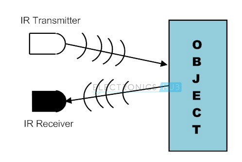
The basic concept of an Infrared Sensor which is used as Obstacle
detector is to transmit an infrared signal, this infrared signal bounces from
the surface of an object and the signal is received at the infrared receiver.
There are five basic elements used in a typical infrared detection
system: an infrared source, a transmission medium, optical component, infrared
detectors or receivers and signal processing. Infrared lasers and Infrared
LED’s of specific wavelength can be used as infrared sources. The three main
types of media used for infrared transmission are vacuum, atmosphere and
optical fibers. Optical components are used to focus the infrared radiation or
to limit the spectral response. Optical lenses made of Quartz, Germanium and
Silicon are used to focus the infrared radiation. Infrared receivers can be
photodiodes, phototransistors etc. some important specifications of infrared
receivers are photosensitivity, detectivity and noise equivalent power. Signal
processing is done by amplifiers as the output of infrared detector is very
small.
Infrared sensors can be passive or active. Passive infrared
sensors are basically Infrared detectors. Passive infrared sensors do not use any
infrared source and detects energy emitted by obstacles in the field of view.
They are of two types: quantum and thermal. Thermal infrared sensors use
infrared energy as the source of heat and are independent of wavelength.
Thermocouples, pyroelectric detectors and bolometers are the common types of
thermal infrared detectors.
Quantum type infrared detectors offer higher detection performance
and are faster than thermal type infrared detectors. The photosensitivity of
quantum type detectors is wavelength dependent. Quantum type detectors are
further classified into two types: intrinsic and extrinsic types. Intrinsic
type quantum detectors are photoconductive cells and photovoltaic cells.
Active infrared sensors consist of two elements: infrared source
and infrared detector. Infrared sources include an LED or infrared laser diode.
Infrared detectors include photodiodes or phototransistors. The energy emitted
by the infrared source is reflected by an object and falls on the infrared
detector.
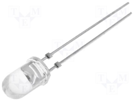
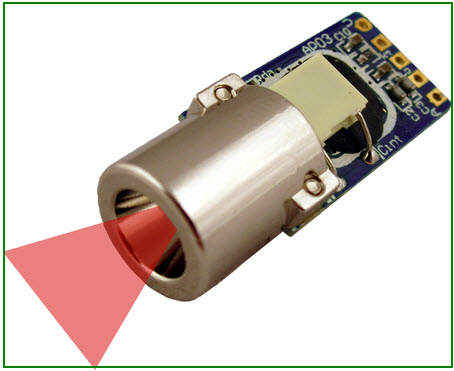
Infrared Transmitter is a light emitting diode (LED) which emits
infrared radiations. Hence, they are called IR LED’s. Even though an IR LED
looks like a normal LED, the radiation emitted by it is invisible to the human
eye.
The picture of a typical Infrared LED is shown below.
There are different types of infrared transmitters depending on
their wavelengths, output power and response time.
A simple infrared transmitter can be constructed using an infrared
LED, a current limiting resistor and a power supply. The schematic of a typical
IR transmitter is shown below.
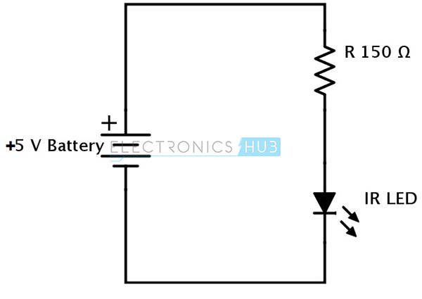
When operated at a supply of 5V, the IR transmitter consumes about
3 to 5 mA of current. Infrared transmitters can be modulated to produce a
particular frequency of infrared light. The most commonly used modulation is
OOK (ON – OFF – KEYING) modulation.
IR transmitters can be found in several applications. Some
applications require infrared heat and the best infrared source is infrared
transmitter. When infrared emitters are used with Quartz, solar cells can be
made.
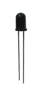
Infrared receivers are also called as infrared sensors as they
detect the radiation from an IR transmitter. IR receivers come in the form of
photodiodes and phototransistors. Infrared Photodiodes are different from
normal photo diodes as they detect only infrared radiation. The picture of a
typical IR receiver or a photodiode is shown below.
Different types of IR receivers exist based on the wavelength,
voltage, package, etc. When used in an infrared transmitter – receiver
combination, the wavelength of the receiver should match with that of the
transmitter.
A typical infrared receiver circuit using a phototransistor is
shown below.
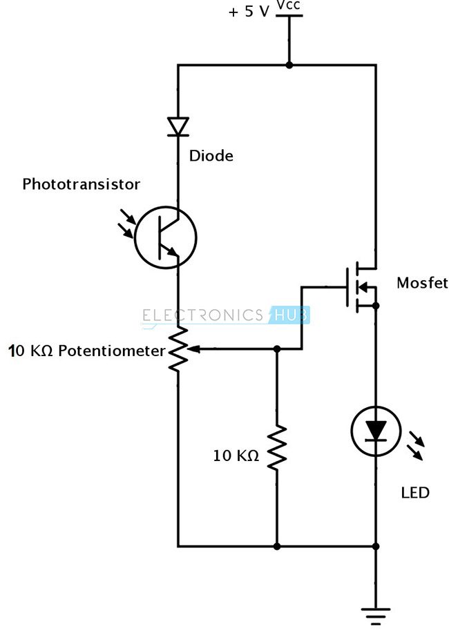
It consists of an IR phototransistor, a diode, a MOSFET, a
potentiometer and an LED. When the phototransistor receives any infrared
radiation, current flows through it and MOSFET turns on. This in turn lights up
the LED which acts as a load. The potentiometer is used to control the
sensitivity of the phototransistor.
The principle of an IR sensor working as an Object Detection
Sensor can be explained using the following figure. An IR sensor consists of an
IR LED and an IR Photodiode; together they are called as Photo – Coupler or Opto
– Coupler.
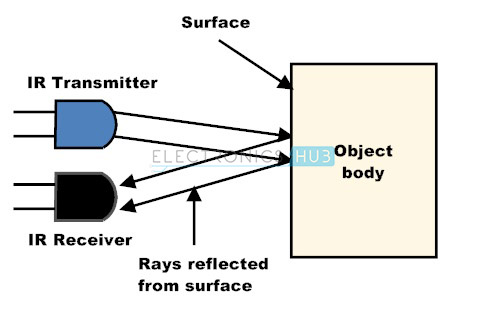
When the IR transmitter emits radiation, it reaches the object and
some of the radiation reflects back to the IR receiver. Based on the intensity
of the reception by the IR receiver, the output of the sensor is defined.
A typical IR sensing circuit is shown below.
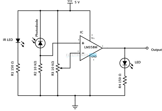
It consists of an IR LED, a photodiode, a potentiometer, an IC
Operational amplifier and an LED.
IR LED emits infrared light. The Photodiode detects the infrared
light. An IC Op – Amp is used as a voltage comparator. The potentiometer is
used to calibrate the output of the sensor according to the requirement.
When the light emitted by the IR LED is incident on the photodiode
after hitting an object, the resistance of the photodiode falls down from a
huge value. One of the input of the op – amp is at threshold value set by the
potentiometer. The other input to the op-amp is from the photodiode’s series
resistor. When the incident radiation is more on the photodiode, the voltage
drop across the series resistor will be high. In the IC, both the threshold
voltage and the voltage across the series resistor are compared. If the voltage
across the resistor series to photodiode is greater than that of the threshold
voltage, the output of the IC Op – Amp is high. As the output of the IC is connected
to an LED, it lightens up. The threshold voltage can be adjusted by adjusting
the potentiometer depending on the environmental conditions.
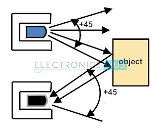
The positioning of the IR LED and the IR Receiver is an important
factor. When the IR LED is held directly in front of the IR receiver, this
setup is called Direct Incidence. In this case, almost the entire radiation
from the IR LED will fall on the IR receiver. Hence there is a line of sight
communication between the infrared transmitter and the receiver. If an object
falls in this line, it obstructs the radiation from reaching the receiver
either by reflecting the radiation or absorbing the radiation.
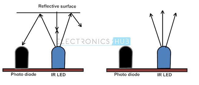
It is universal that black color absorbs the entire radiation incident
on it and white color reflects the entire radiation incident on it. Based on
this principle, the second positioning of the sensor couple can be made. The IR
LED and the photodiode are placed side by side. When the IR transmitter emits
infrared radiation, since there is no direct line of contact between the
transmitter and receiver, the emitted radiation must reflect back to the
photodiode after hitting any object. The surface of the object can be divided
into two types: reflective surface and non-reflective surface. If the surface
of the object is reflective in nature i.e. it is white or other light color,
most of the radiation incident on it will get reflected back and reaches the
photodiode. Depending on the intensity of the radiation reflected back, current
flows in the photodiode.
If the surface of the object is non-reflective in nature i.e. it
is black or other dark color, it absorbs almost all the radiation incident on
it. As there is no reflected radiation, there is no radiation incident on the photodiode
and the resistance of the photodiode remains higher allowing no current to
flow. This situation is similar to there being no object at all.
The pictorial representation of the above scenarios is shown
below.
The positioning and enclosing of the IR transmitter and Receiver
is very important. Both the transmitter and the receiver must be placed at a
certain angle, so that the detection of an object happens properly. This angle
is the directivity of the sensor which is +/- 45 degrees.
The directivity is shown below.
In order to avoid reflections from surrounding objects other than
the object, both the IR transmitter and the IR receiver must be enclosed
properly. Generally the enclosure is made of plastic and is painted with black
color.
Infrared IR Sensor Circuit Diagram and Working Principle
An infrared sensor is an electronic device, that emits in
order to sense some aspects of the surroundings. An IR sensor can measure the
heat of an object as well as detects the motion.These types of sensors measures
only infrared radiation, rather than emitting it that is called as a passive IR sensor. Usually in the infrared spectrum, all the
objects radiate some form of thermal radiations. These types of radiations
are invisible to our eyes, that can be detected by an infrared sensor.The
emitter is simply an IR LED (Light Emitting Diode) and the detector is simply an IR
photodiode which is sensitive to IR light of the same wavelength as that
emitted by the IR LED. When IR light falls on the photodiode, The resistances
and these output voltages, change in proportion to the magnitude of the IR
light received.
IR Sensor
IR Sensor Circuit Diagram and Working Principle
An infrared sensor circuit is one of the basic and popular
sensor module in an electronic device. This sensor is analogous to human’s
visionary senses, which can be used to detect obstacles and it is one of the
common applications in real time.This circuit comprises of the following
components
LM358 IC 2 IR transmitter and receiver pair
Resistors of the range of kilo ohms.
Variable resistors.
LED (Light Emitting Diode).

IR Sensor Circuit
In this project, the transmitter section includes an IR sensor,
which transmits continuous IR rays to be received by an IR receiver module. An
IR output terminal of the receiver varies depending upon its receiving of IR
rays. Since this variation cannot be analyzed as such, therefore this output
can be fed to a comparator circuit. Here anoperational amplifier (op-amp) of LM 339 is used as
comparator circuit.
When the IR receiver does not receive a signal, the potential at
the inverting input goes higher than that non-inverting input of the comparator
IC (LM339). Thus the output of the comparator goes low, but the LED does not
glow. When the IR receiver module receives signal to the potential at the
inverting input goes low. Thus the output of the comparator (LM 339) goes high
and the LED starts glowing. Resistor R1 (100 ), R2 (10k ) and R3 (330) are used
to ensure that minimum 10 mA current passes through the IR LED Devices like
Photodiode and normal LEDs respectively. Resistor VR2 (preset=5k ) is used to
adjust the output terminals. Resistor VR1 (preset=10k ) is used to set the
sensitivity of the circuit Diagram. Read more about IR sensors.
Different Types of IR Sensors and Their Applications
IR sensors are classified into different types depending on the
applications. Some of the typical applications of different types of sensors are
The speed sensor is used for synchronizing the speed of multiple
motors. The temperature sensor is
used for industrial temperature control. PIR sensor is
used for automatic door opening system and Ultrasonic sensor are used for distance measurement.
IR Sensor Applications
IR sensors are used in various Sensor based projects and also in various electronic
devices which measures the temperature that are discussed in the below.
Radiation Thermometers
IR sensors are used in radiation thermometers to measure the
temperature depend upon the temperature and the material of the object and
these thermometers have some of the following features
Measurement without direct contact with the object
Faster response
Easy pattern measurements
Flame Monitors
These types of devices are used for detecting the light emitted
from the flames and to monitor how the flames are burning. The Light emitted
from flames extend from UV to IR region types. PbS, PbSe, Two-color detector,
pyro electric detector are some of the commonly employed detector used in flame
monitors.
Moisture Analyzers
Moisture analyzers use wavelengths which are absorbed by the
moisture in the IR region. Objects are irradiated with light having these
wavelengths(1.1 µm, 1.4 µm, 1.9 µm, and 2.7µm) and also with reference
wavelengths. The Lights reflected from the objects depend upon the moisture
content and is detected by analyzer to measure moisture (ratio of reflected
light at these wavelengths to the reflected light at reference wavelength). In
GaAs PIN photodiodes, Pbs photoconductive detectors are employed in moisture
analyzer circuits.
Gas Analyzers
IR sensors are used in gas analyzers which use absorption
characteristics of gases in the IR region. Two types of methods are used to
measure the density of gas such as dispersive and non dispersive.

Gas Analizer
Dispersive: An Emitted light
is spectroscopically divided and their absorption characteristics are used to
analyze the gas ingredients and the sample quantity.
Non dispersive: It is
most commonly used method and it uses absorption characteristics without
dividing the emitted light. Non dispersive types use discrete optical band pass
filters, similar to sunglasses that are used for eye protection to filter out
unwanted UV radiation.
This type of configuration is commonly referred to as non
dispersive infrared (NDIR) technology. This type of analyzer is used for
carbonated drinks, whereas non dispersive analyzer is used in most of the
commercial IR instruments, for an automobile exhaust gas fuel leakages.
IR Imaging Devices
IR image device is one of the major applications of IR waves,
primarily by virtue of its property that is not visible. It is used for thermal
imagers, night vision devices, etc.

IR Imaging Devices
For examples Water, rocks, soil, vegetation, an atmosphere, and
human tissue all features emit IR radiation. The Thermal infrared detectors
measure these radiations in IR range and map the spatial temperature
distributions of the object/area on an image. Thermal imagers usually composed
of a Sb (indium antimonite), Gd Hg (mercury-doped germanium), Hg Cd Te
(mercury-cadmium-telluride) sensors.
An electronic detector is cooled to low temperatures using liquid
helium or liquid nitrogen’s. Then the Cooling the detectors ensures that
the radiant energy (photons) recorded by the detectors comes from the terrain
and not from the ambient temperature of objects within the scanner itself an IR
imaging electronic devices.
Thus, this is all about IR sensor circuit with working and
applications. These sensors are used in many sensor basedelectronics projects. We believe that, you might have got a
better understanding of this IR sensor and its working principle.Furthermore,
any doubts regarding this article or projects please give your feedback by
commenting in the comment section below.Here is a question for you, can the
infrared thermometer operate in complete darkness?
Photo Credits:
IR Sensor Circuit by blogspot
Gas Analyzer by imimg
IR Sensor by shopify
Light Dependent Resistor | LDR and Working Principle of LDR
What is a Light
Dependent Resistor or a Photo Resistor?
A Light
Dependent Resistor (LDR) or a photo resistor is a
device whose resistivity is a function of the incident electromagnetic
radiation. Hence, they are light sensitive devices. They are also called as
photo conductors, photo conductive cells or simply photocells. They are made up
of semiconductor
materials having high resistance. There are many different symbols used to
indicate a LDR,
one of the most commonly used symbol is shown in the figure below. The arrow
indicates light falling on it.
Working Principle of
LDR
A light
dependent resistor
works on the principle of photo conductivity.
Photo conductivity is
an optical phenomenon in which the materials conductivity is increased when
light is absorbed by the material. When light falls i.e. when the photons fall
on the device, the electrons in the valence band of the semiconductor
material are excited to the conduction band. These photons in the incident
light should have energy greater than the band gap of the semiconductor
material to make the electrons jump from the valence band to the conduction
band. Hence when light having enough energy strikes on the device, more and
more electrons are excited to the conduction band which results in large number
of charge carriers. The result of this process is
more and more current starts
flowing throgh the device when the circuit is closed and hence it is said that
the resistance
of the device has been decreased. This is the most common working
principle of LDR
Characteristics of LDR
LDR’s are light dependent devices whose resistance
is decreased when light falls on them and that is increased in the dark. When a
light dependent resistor
is kept in dark, its resistance is very high. This resistance is called as dark
resistance.
It can be as high as 1012 Ω and if the device is allowed to absorb
light its resistance
will be decreased drastically. If a constant voltage
is applied to it and intensity of light is increased the current starts
increasing. Figure below shows resistance
vs. illumination curve for a particular LDR.
 Photocells or
LDR’s are non linear devices. There sensitivity varies with the wavelength of
light incident on them. Some photocells might not at all response to a certain
range of wavelengths. Based on the material used different cells have different
spectral response curves.
Photocells or
LDR’s are non linear devices. There sensitivity varies with the wavelength of
light incident on them. Some photocells might not at all response to a certain
range of wavelengths. Based on the material used different cells have different
spectral response curves.
Photocells or
LDR’s are non linear devices. There sensitivity varies with the wavelength of
light incident on them. Some photocells might not at all response to a certain
range of wavelengths. Based on the material used different cells have different
spectral response curves.
When light is incident
on a photocell it usually takes about 8 to 12 ms for the change in resistance
to take place, while it takes one or more seconds for the resistance
to rise back again to its initial value after removal of light. This phenomenon
is called as resistance
recovery rate. This property is used in audio compressors. Also, LDR’s
are less sensitive than photo diodes and photo transistor. (A photo diode
and a photocell (LDR) are not the same, a photo-diode is a p-n junction semiconductor
device that converts light to electricity, whereas a photocell is a passive
device, there is no p-n junction in this nor it “converts” light to
electricity). Types of Light Dependent Resistors: Based on the materials used
they are classified as:
1. Intrinsic photo resistors (Un
doped semiconductor): These are made of pure semiconductor
materials such as silicon or germanium. Electrons get excited from valance band
to conduction band when photons of enough energy fall on it and number charge
carriers is increased.
2. Extrinsic photo resistors:
These are semiconductor
materials doped with impurities which are called as dopants. Theses dopants
create new energy bands above the valence band which are filled with electrons.
Hence this reduces the band gap and less energy is required in exciting them.
Extrinsic photo resistors are
generally used for long wavelengths.
Construction of a
Photocell
The structure of a light dependent resistor
consists of a light sensitive material which is deposited on an insulating
substrate such as ceramic. The material is deposited in zigzag pattern in order
to obtain the desired resistance
& power rating. This zigzag area separates the metal deposited areas into
two regions. Then the ohmic contacts are made on the either sides of the area.
The resistances
of these contacts should be as less as possible to make sure that the resistance
mainly changes due to the effect of light only. Materials normally used are
cadmium sulphide, cadmium selenide, indium antimonide and cadmium sulphonide.
The use of lead and cadmium is avoided as they are harmful to the environment. 
Applications of LDR
LDR’s have low cost and
simple structure. They are often used as light sensors. They are used when
there is a need to detect absences or presences of light like in a camera light
meter. Used in street lamps, alarm clock, burglar alarm circuits, light
intensity meters, for counting the packages moving on a conveyor belt, etc.
What is a Light Dependent Resistor and Its Applications

Light Dependent Resistor
The
dominant of street lights, outside lights, a number of indoor home appliances,
and so on are typically operated and maintained manually on many occasions.
This is not only risky, however additionally leads to wastage of power with the
negligence of personnel or uncommon circumstances in controlling these electrical
appliances ON and OFF.
Hence, we can utilize the light sensor circuit for automatic switch OFF the
loads based on daylight’s intensity by employing a light sensor. This article
discusses in brief about what is a light dependent resistor, how to make a
light dependent resistor circuit and its applications.
What is a Light Dependent Resistor?
An
LDR or light dependent resistor is also known as photo resistor,
photocell, photoconductor.It is a one type of resistor whose resistance varies
depending on the amount of light falling on its surface. When the light falls
on the resistor, then the resistance changes. These resistors are often used in
many circuits where it is required to sense the presence of light. These resistors
have a variety of functions and resistance. For instance, when the LDR is in
darkness, then it can be used to turn ON a light or to turn OFF a light when it
is in the light. A typical light dependent resistor has a resistance in the
darkness of 1MOhm, and in the brightness a resistance of a couple of KOhm
Working Principle of LDR
This
resistor works on the principle of photo conductivity. It is nothing but, when
the light falls on its surface, then the material conductivity reduces and also
the electrons in the valence band of the device are excited to the conduction
band. These photons in the incident light must have energy greater than the
band gap of the semiconductor material.This makes the electrons to jump from
the valence band to conduction.

Working Principle of LDR
These
devices depend on the light, when light falls on the LDR then the resistance
decreases, and increases in the dark.When a LDR is kept in the dark place, its
resistance is high and, when the LDR is kept in the light its resistance will
decrease.

Variation of LDR Resistance with Variation in Light Intensity
If
a constant “V’ is applied to the LDR, the intensity of the light increased and
current increases. The figure below shows the curve between resistance Vs
illumination curve for a particular light dependent resistor.

Light Intensity vs LDR Resistance
Types of light Dependent Resistors
Light
dependent resistors are classified based on the materials used.
Intrinsic Photo Resistors
These
resistors are pure semiconductor devices like silicon or germanium. When the
light falls on the LDR, then the electrons get excited from the valence band to
the conduction band and number of charge carriers increases.
Extrinsic Photo Resistors
These
devices are doped with impurities and these impurities creates a new energy
bands above the valence band. These bands are filled with electrons. Hence this
decrease the band gap and small amount of energy is required in moving them.
These resistors are mainly used for long wavelengths.
Circuit Diagram of a Light Dependent Resistor
The
circuit diagram of a LDR is shown below. When the light intensity is low, then
the resistance of the LDR is high. This stops the current flow to the base
terminal of the transistor. So, the LED does not light. However, when the light
intensity onto the LDR is high, then the resistance of the LDR is low.So
current flows onto the base of the first transistor and then the second
transistor.Consequently the LED lights.Here, a preset resistor is used to turn
up or down to increase or decrease the resistance.

Light Dependent Resistor Circuit
Light Dependent Resistor Applications
Light
dependent resistors have a low cost and simple structure. These resistors are
frequently used as light sensors. These resistors are mainly used when there is
a need to sense the absence and presence of the light such as burglar alarm
circuits, alarm clock, light intensity meters, etc. LDR resistors mainly
involves in various electrical
and electronic projects. For better understanding of this concept, here
we are explainingsome real time projects where the LDR resistors are used.
Security System Controlled by An Electronic
Eye
This
security system controlled by an electronic eye project is based on photo
sensing arrangement. The proposed system uses a 14-stage ripple carry binary
counter to sense the intensity of light using LDR. The o/p makes a relay and
buzzer for the required action. This project is very useful to deter burglars
from shopping malls, banks and jewelry shops, etc.
This
project uses a light dependent resistor. When light falls on the LDR sensor,
then the resistance of the sensor decreases, which lead to activate an alarm to
give an alert to the user. This project is suitable in the application of
providing security system for lockers, cash boxes which can be found in the
banks, shopping malls, jewel shops.
The
circuit of this project is placed inside of the cash box in shopping malls or
inside of the lockers in banks in such a way that, when a burglar opens the
cash box or locker and uses a torch light to search the valuables. When the
light falls on the circuit which includes an electronic eye and gives a command
to the ripple counter. This triggers the alarm and shows a burglary attempt. A
lamp is also used to indicate the theft when light falls on the sensor.

Comments
Post a Comment